Subsections
 | Forces
 | Friction |
|
 | Torque |
 | Simple Machines
 | The Inclined Plane |
 | Levers |
 | The Wheel and Axle
 | Gears and Belts |
|
 | Cams and Cranks |
 | Pulleys |
 | The Screw |
 | Inertia
 | Rotational Inertia |
|
|
 | Springs
 | Rubber Bands |
|
 | Counterweights |
Basic MechanicsThe branch of physics that deals with the action of forces on matter is referred to as mechanics. All considerations of motion are addressed by mechanics, as well as the transmission of forces through the use of simple machines. In our class, the goal is a mechanical goal (placing blocks into a bin) and electronics are used to control the mechanics.
While it is not necessary to sit down and draw free body diagrams or figure out the static coefficient of friction between the LEGO tires and the game board, it is helpful to keep certain mechanical concepts in mind when constructing a robot. If a robot's tires are spinning because they do not grip the floor, then something must be done to increase the friction between the tires and the floor. One solution is to glue a rubber band around the circumference of the tire. That problem/solution did not require an in-depth study of physics. Simply considering the different possibilities can lead to more mechanically creative robots.
Describing motion involves more than just saying that an object moved three feet to the right. The magnitude and direction of the displacement are important, but so are the characteristics of the object's velocity and acceleration. To understand these concepts, we must examine the nature of force. Changes in the motion of an object are created by forces.
Forces
Whether a force is the push of a motor or the pull of gravity or muscles, the important characteristics are the magnitude and direction of the force, and the mass and previous state of motion of the object being affected. By pushing on a moving car, one can either cause it to gain speed or come to a stop, depending on which direction the force is applied, and that same force applied to a feather would be expected to more drastically affect the motion of the feather.
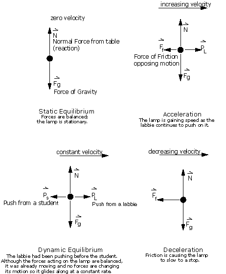
It is common practice to determine the expected changes in motion that an object will experience due to a particular force with the aid of a "free body" diagram. A diagram can tell us at a glance in which direction we would expect an object to accelerate or decelerate. A free body diagram shows all of the forces acting on an object, even if their effects are balanced out by another force. We will use free body diagrams to consider different situations involving the lamp that you find at your lab station (Figure 3.1).
One force that always acts on the lamp is gravity. This familiar force would accelerate the lamp downward toward the center of the earth if left unchallenged. However, when the lamp is placed on a table it does not move downward because the table holds it up. The lamp is pushing down on the table and the table is pushing up on the lamp. This pair of forces is an action-reaction pair: equal and opposite forces acting on two different objects in contact. The reaction force from the table is called the normal force because this force is oriented normal (perpendicular) to the surface of the table. The arrows representing the forces are labeled. The symbols over the labels remind us that the forces are vector quantities and that the direction in which the force is applied is important. The length of the force vector should be proportional to their magnitudes.
Figure 3.1: Free Body Diagrams
 |
In Figure 3.1 the lamp was represented by a simple dot. We assumed that the lamp was rigid and that a downward force applied at one particular spot on the lamp would yield the same result as a similar downward force applied at a different place on the lamp. Actually, in order for a force of equal magnitude and direction to affect an object's motion in the same manner it must be applied along the same line of action as the original force (see Figure 3.2. If the original force had been a tug on a string tied to the lamp, then it makes sense that grabbing the string at a different distance away from the lamp to tug should not make a difference provided that the direction and magnitude do not change.
Figure 3.2: Line of Action
 |
Friction The normal force from the table's surface is a reaction force only. Without the downward force on the table from the object resting its weight on the surface, the normal force does not exist. This type of behavior is also descriptive of frictional forces.
Friction is opposition to motion, so if nothing is trying to move there will be no friction. However, friction will be present when motion is attempted, even if the object is not yet moving. There are two different types of friction: static, which acts before the object begins to move, and dynamic, which acts after the object begins moving. Static friction is usually stronger than dynamic friction.
Figure 3.3: "Close Up" of surfaces in contact
 |
Friction occurs because the surfaces in contact are not smooth. The small ridges on the different surfaces catch, and in order for the objects to move, these ridges must be broken off or the object must ramp up and over the obstructions. By adding a lubricant between the two layers, it is possible to "float" one layer high enough to miss some of the obstructions to motion. At an atomic level, cold joints may form where the atoms from one object's surface may form weak bonds with the atoms on the surface of the other object. These bonds must also be broken in order for the object to move. All of this resistance to motion is called friction. Friction is very important because it not only inhibits motion, friction also makes motion possible.
The robots built in ELEC 201 will probably be wheeled vehicles, and without friction those wheels would just spin in place without moving the robot anywhere. In order to increase the friction between the wheels and the game board one might use wheels made of a different material or add a rubber band around the wheel's circumference. Friction is not desirable in all cases. When it comes to axles spinning inside of holes in beams or gears rubbing up against beams or even gears pushing against each other, friction can cause two identically constructed gear trains to behave differently. Friction can even render the whole assembly ineffective. With the 6 Volt DC Mabuchi motors that were used in the 1994 class, a worm gear in a drive train created so much friction that more of the motor's effort went towards overcoming friction than actually driving the robot.
Torque
Figure 3.4: Illustrating Torque
 |
To understand the importance of using a line of action when considering a force, think of a yard stick which has been pinned at the center. The yard stick is free to pivot around its center, so a downward force applied at different places (and thus through different lines of action) will yield different results. Pressing down directly over the pivot does not cause the stick to move or rotate, while pressing down at one end causes the stick to rotate about the pivot. By pressing down at the end, we have applied a torque to the stick and have caused it to rotate.
A torque is a force applied at a distance from a pivot. When describing torques, one must include magnitude, direction, and perpendicular distance from the pivot. For torques the line of action is a circle centered on the pivot. As torque is a product of force and distance, one may be "traded" for the other. By applying more force closer to the pivot, one may produce the same torque. This concept of "trading" distance traveled/applied for force experienced/applied is key to many simple machines.
Simple Machines Complex machines are made up of moving parts such as levers, gears, cams, cranks, springs, belts, and wheels. Machines deliver a certain type of movement to a desired location from an input force applied somewhere else. Some machines simply convert one type of motion to another type (rotary to linear). While there is a seemingly endless variety of machines, they are all based upon simple machines. Simple machines include inclined planes, levers, wheel and axle, pulleys, and screws.
It is important to remember that all machines are limited in their efficiency. No machine is 100 percent efficient in its efforts, so the mechanical advantaged gained must be considered worthwhile of the extra energy that will be required to accomplish the job.
The Inclined Plane
Figure 3.5: Inclined Plane
 |
In an inclined plane the force required to raise an object a given distance is decreased by increasing the distance over which that force must be applied. Imagine lifting something twice your weight to a 4 foot high shelf. Now imagine rolling the same mass up a gently sloping surface. The latter would be much easier. Inclined planes are commonly put to use in cutting devices and often two inclined planes are put back to back to form a wedge. In a wedge forward movement is converted into a parting movement acting perpendicular to the face of the blade (see Figure 3.6). A zipper is simply a combination of two lower wedges for closing and an upper wedge for opening (Figure 3.6).
Figure 3.6: The Inclined Plane at Work
 |
LeversA lever has three points of interest: the fulcrum, the load, and the effort. The fulcrum is the point around which the lever pivots rotationally. The load is what we wish to manipulate with the lever, and the load is described by magnitude, direction, and position relative to the fulcrum. The effort also has a magnitude, direction, and position with respect to the fulcrum. A lever is commonly used to change the direction of movement, and to trade the magnitude of the effort for the distance over which the effort is applied.
Figure 3.7: Classes of Levers
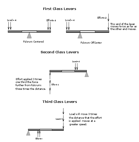 |
As shown in Figure 3.7, there are three different classes of levers defined by the relative positions of the fulcrum, effort, and load. A first class lever has the fulcrum positioned between the effort and the load. Examples of first class levers include: a balance, a crow bar, and scissors. In a second class lever the load is placed between the fulcrum and the effort. Examples of second class levers include: a wheelbarrow, a bottle opener, and a nutcracker. Third class levers place the effort between the fulcrum and the load. Examples of a third class lever are a hammer, a fishing rod, and tweezers. Most machines that employ levers use a combination of several levers, often of different classes.
The Wheel and AxleIn both levers and the inclined plane, you gain in force what you lose in distance traveled. With wheels and axles the same is true; the movement of the wheel is converted to a shorter but more powerful movement at the axle. The wheel and axle can be thought of as simply a circular lever, as shown in Figure 3.8. Many common items rely on the wheel and axle such as the screwdriver, the steering wheel, the wrench, and the faucet.
Figure 3.8: The Wheel and Axle
 |
Gears and BeltsA wheel and axle assembly becomes especially useful when gears and belts are brought into the picture. Gears can be used to change the direction or speed of movement, but changing the speed of rotation inversely affects the force transmitted. A small gear meshed with a larger gear will turn faster, but with less force. There are four basic types of gears: spur gears, rack and pinion gears, bevel gears, and worm gears. Spur gears are probably the type of gear that most people picture when they hear the word. The two wheels are in the same plane (the axles are parallel). With rack and pinion gears there is one wheel and one rack, a flat toothed bar that converts the rotary motion into linear motion. Bevel gears are also known as pinion and crown or pinion and ring gears. In bevel gears, two wheels intermesh at an angle changing the direction of rotation (the axles are not parallel); the speed and force may also be modified, if desired. Worm gears involve one wheel gear (a pinion) and one shaft with a screw thread wrapped around it. Worm gears change the direction of motion as well as the speed and force. Belts work in the same manner as spur gears except that they do not change the direction of motion.
In both gears and belts, the way to alter speed and force is through the size of the two interacting wheels. In any pair, the bigger wheel always rotates more slowly, but with more force. This "tradeoff" between force and speed comes from the difference in the distance between the point of rotation and the axle between the two wheels. On both the big and the small gear, the linear velocity at the point of contact for the wheels is equal. If it was unequal and one gear were spinning faster than the other at the point of contact then it would rip the teeth right off of the other gear. As the circumference of the larger gear is greater, a point on the outside of the larger gear must cover a greater distance than a point on the smaller gear to complete a revolution. Therefore the smaller gear must complete more revolutions than the larger gear in the same time span. (It's rotating more quickly.) The force applied to the outer surface of each wheel must also be equal otherwise one of them would be accelerating more rapidly than the other and again the teeth of the other wheel would break. The forces of interest however are not the forces being applied to the outer surfaces of the wheels, but rather the forces on the axles. Returning to the concept of levers, we know that the distance at which the force is applied affects the force yielded, and a wheel and axle works like a lever. Equal forces are being applied to each wheel, but on the larger wheel that force is being applied over a greater distance. Thus for the larger wheel the force on the axle is greater than the force on the axle for the smaller wheel.
Cams and Cranks
Both cams and cranks are useful when a repetitive motion is desired. Cams make rotary motion a little more interesting by essentially moving the axle off-center. Cams are often used in conjunction with a rod. One end of the rod is held flush against the cam by a spring. As the cam rotates the rod remains stationary until the "bump" of the cam pushes the rod away from the cam's axle.
Figure 3.9: Cams and Cranks
 |
Cranks convert rotary motion into a piston-like linear motion. The best examples of cranks in action are the drive mechanism for a steam locomotive and the automobile engine crankshaft. In a crank, the wheel rotates about a centered axle, while an arm is attached to the wheel with an off-centered peg. This arm is attached to a rod fixed in a linear path. A crank will cause the rod to move back and forth, and if the rod is pushed back and forth, it will cause the crank to turn. On the other hand, cams can move their rods, but rods cannot move the cams. Cams can be used to create either a linear repetitive motion such as the one illustrated in Figure 3.9, or a repetitive rotational motion such as the one shown in Figure 3.15.
Pulleys
Figure 3.10: Pulleys
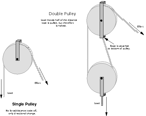 |
Pulleys can be used to simply change the direction of an applied force or to provide a force/distance tradeoff in addition to a directional change, as shown in Figure 3.10. Pulleys are very flexible because they use ropes to transfer force rather than a rigid object such as a board or a rod. Ropes can be routed through virtually any path. They are able to abruptly change directions in three-dimensions without consequence. Ropes can be wrapped around a motor's shaft and either wound up or let out as the motor turns.
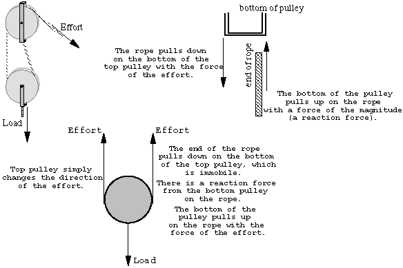
Figure 3.11: How Compound Pulleys Work
 |
Ropes also have the advantage that their performance is not affected by length. If a lever arm was extremely long, then it would be unable to handle the magnitude of forces that a shorter version could withstand. In a lever, to move a given distance next to the fulcrum, the end of the lever must move a distance proportional to its length. As the length of the lever increases, it becomes more likely that the lever will break somewhere along its length.
Figure 3.11 illustrates how a compound pulley `trades' force for distance through an action/reaction force pair. In a double pulley, as the rope passes over the pulley the force is transmitted entirely but the direction has changed. The effort is now pulling up on the left side of the bottom pulley. Now, for a moment forget that the end of the rope is tied to the bottom of the top pulley. The mechanics are the same if the rope is fixed to the ceiling. The important thing is that the end of the rope is immobile. The effort is once again transmitted entirely as the rope passes over the bottom pulley and there is a direction change. The end of the rope is attached to the ceiling so the rope is pulling down on the ceiling with the force of the effort (and half of the force of the load). We assume that the ceiling holds up, so this must mean that there is a force balancing out this downward force. The ceiling pulls up on the rope as a reaction force. This upward force is equal to the effort and now there is an upward force on the right side of the bottom pulley. From the perspective of a free-body diagram the compound pulley system could be replaced by tying two ropes to the load and pulling up on each with a force equal to the effort.
The disadvantages of pulleys, in contrast to machines that use rigid objects to transfer force, are slipping and stretching. A rope will permanently stretch under tension, which may affect the future performance of a device. If a line becomes slack, then the operation of a machine may change entirely. Also, ropes will slip and stick along pulley wheels just like belts. One solution to the problems associated with rope is to use chain. Chain is pliable like rope, and is able to transfer force through many direction changes, but the chain links are inflexible in tension, so that the chain will not stretch. Chains may also be made to fit on gears so that slipping is not a problem.
The Screw
Figure 3.12: The Screw
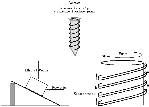 |
The screw is basically an inclined plane (see Figure 3.12) wrapped around a cylinder. In an inclined plane, a linear force in the horizontal plane is converted to a vertical "lifting" force. With a screw, a rotary force in the horizontal plane is converted to a vertical "lifting" force.
When a wood screw is turned, the threads of the screw push up on the wood. A reaction force from the wood pushes back down on the screw threads and in this way the screw moves down even though the force of turning the screw is in the horizontal plane. Screws are known for high friction, which is why they are used to hold things together. This is true for the LEGO worm gears used in ELEC 201. The friction between these gears and others can take away from the force transmitted through them.
Inertia
Inertia is a property of all matter: a resistance to changes in motion. To be clear, a change in motion is not just beginning to move from a stop. Slowing down, speeding up, and changing direction are all changes in motion. The only way to change a object's motion is to apply a force to that object. A book slid across a table only comes to a stop because of the frictional forces acting on it. Inertia is proportional to mass, so a more massive object is more difficult to move or stop than a lighter one (even on a frictionless surface).
Figure 3.13: Flywheel
 |
Rotational InertiaJust as a book slides until a force opposes its motion, a disc will spin until its rotation is opposed by some force. This property is aptly named rotational inertia. One of the most common applications of rotational inertia is shown in Figure 3.13. Many children's toys use rotational inertia. In friction-drive cars, the child pushes the car forward several times to set an internal flywheel in motion. When the car is put down, the flywheel is still spinning and the car moves. This is an interesting way to store energy -- in kinetic, rather than potential format. Rotational inertia is also used to avoid changes in motion for such objects as record players, where it is important to rotate at a constant speed. A flywheel could conceivably be used to store energy to keep an ELEC 201 robot operating after its motors were required to be shut off.
SpringsA favorite device for storing potential energy is the spring. Everything from clocks to catapults make use of springs. There are two distinctive forms of springs: the familiar coil and the bending bar. A common use for springs is to return something to its original position. A more interesting application is to use them to measure force -- springs in scales. The third use is to store energy. All springs perform all three functions all of the time, but specific devices are built to exploit certain functions of the spring.
Figure 3.14: Bar Spring
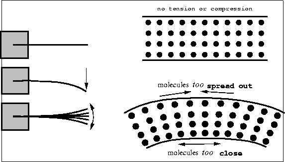 |
A coil spring works for more or less the same reason as a bar spring, it's just in a different shape. To understand a spring, one must zoom in to the microscopic level where molecules interact. Molecules are held together in rigid bodies because of electromagnetic forces. Some of these forces are repulsive, and some of them are attractive. Normally they balance out so that the molecules are evenly spaced within an object; however, by bending a bar, some molecules are forced farther apart and others are shoved closer together. Where the molecules have been spread out, the attractive forces strive to return the original spacing. Where molecules have been forced together, the repulsive forces work to return the object to the original shape.
Rubber Bands A rubber band is just a kind of spring. A rubber band is slightly more versatile than a metal spring because of its flexibility, just as pulleys are more versatile than their rigid cousin the lever. Using springs in ELEC 201 might take a small amount of imagination, but rubber bands almost scream to be used. There might be several small tasks that a robot performs only once during a round. It would not make sense to devote an entire motor to such a task. It's not worth carrying around the extra weight if the task could be accomplished just as well with rubber bands.
Figure 3.15: Using a Cam and a Rubber Band
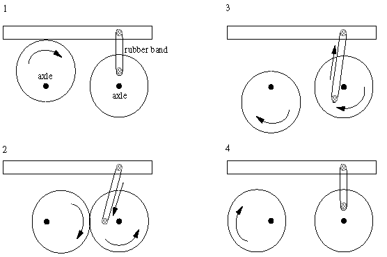 |
Rubber bands also prove useful in the case of repetitive motions. Rather than turning a motor forward then backwards then forwards and so on, one could make use of a cam and a rubber band to allow the motor to always turn in one direction. Look at the assembly in Figure 3.15 for an example.
Counterweights
Counterweighting is a necessary evil in constructing even a simple robot. Examples of common counterweights are shown in Figure 3.16. If a robot that has been traveling along at high speed suddenly comes to a halt, there is danger of the robot overturning if the location of the robot's center of mass has not been well placed. The ELEC 201 robots carry around a fairly massive battery, and its placement within the robot's structure is important. When an arm extends, the robot should remain stable. This is accomplished through the use of counterweights.
Figure 3.16: Some Common Counterweights
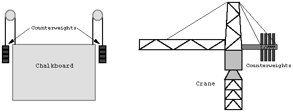 |
Counterweighting might also prove useful to raise a bin carrying blocks. Rather than committing an entire motor to raising a bin, a set of counterweights known to be heavier than the bin plus contents could be suspended until the time when the bin should rise. Of course if a motor was used to take care of the counterweights then no motors have been saved. A motor could be used for more than one task if a mechanical transmission (see Figure 8.15) was employed. Another solution would be to use the high current LED outputs to operate a solenoid.

Subsections
 | What is Charge?
 | Charge exists. |
 | Charge comes in two styles. |
 | Charge is conserved. |
|
 | Voltage |
 | Current |
 | Batteries |
 | Circuit Elements
 | Resistors
 | Ohm's Law |
 | Power |
 | Combinations of Resistors |
|
 | Capacitors
 | Combinations of Capacitors |
|
 | Inductors
 | Combinations of Inductors |
|
|
 | Semiconductor Devices
 | The Truth About Charge |
 | Silicon |
 | Diodes |
|
Basic Electronics The goal of this chapter is to provide some basic information about electronic circuits. We make the assumption that you have no prior knowledge of electronics, electricity, or circuits, and start from the basics. This is an unconventional approach, so it may be interesting, or at least amusing, even if you do have some experience. So, the first question is ``What is an electronic circuit?'' A circuit is a structure that directs and controls electric currents, presumably to perform some useful function. The very name "circuit" implies that the structure is closed, something like a loop. That is all very well, but this answer immediately raises a new question: "What is an electric current?" Again, the name "current" indicates that it refers to some type of flow, and in this case we mean a flow of electric charge, which is usually just called charge because electric charge is really the only kind there is. Finally we come to the basic question:
What is Charge?No one knows what charge really is anymore than anyone knows what gravity is. Both are models, constructions, fabrications if you like, to describe and represent something that can be measured in the real world, specifically a force. Gravity is the name for a force between masses that we can feel and measure. Early workers observed that bodies in "certain electrical condition" also exerted forces on one another that they could measure, and they invented charge to explain their observations. Amazingly, only three simple postulates or assumptions, plus some experimental observations, are necessary to explain all electrical phenomena. Everything: currents, electronics, radio waves, and light. Not many things are so simple, so it is worth stating the three postulates clearly.Charge exists. We just invent the name to represent the source of the physical force that can be observed. The assumption is that the more charge something has, the more force will be exerted. Charge is measured in units of Coulombs, abbreviated C. The unit was named to honor Charles Augustin Coulomb (1736-1806) the French aristocrat and engineer who first measured the force between charged objects using a sensitive torsion balance he invented. Coulomb lived in a time of political unrest and new ideas, the age of Voltaire and Rousseau. Fortunately, Coulomb completed most of his work before the revolution and prudently left Paris with the storming of the Bastille.
Charge comes in two styles.We call the two styles positive charge, , and (you guessed it) negative charge, . Charge also comes in lumps of -19C , which is about two ten-million-trillionths of a Coulomb. The discrete nature of charge is not important for this discussion, but it does serve to indicate that a Coulomb is a LOT of charge.
Charge is conserved.You cannot create it and you cannot annihilate it. You can, however, neutralize it. Early workers observed experimentally that if they took equal amounts of positive and negative charge and combined them on some object, then that object neither exerted nor responded to electrical forces; effectively it had zero net charge. This experiment suggests that it might be possible to take uncharged, or neutral, material and to separate somehow the latent positive and negative charges. If you have ever rubbed a balloon on wool to make it stick to the wall, you have separated charges using mechanical action.
Those are the three postulates. Now we will present some of the experimental findings that both led to them and amplify their significance.
Voltage
First we return to the basic assumption that forces are the result of charges. Specifically, bodies with opposite charges attract, they exert a force on each other pulling them together. The magnitude of the force is proportional to the product of the charge on each mass. This is just like gravity, where we use the term "mass" to represent the quality of bodies that results in the attractive force that pulls them together (see Fig. 4.1).
Figure 4.1: Opposite charges exert an attractive force on each other, just like two masses attract. External force is required to hold them apart, and work is required to move them farther apart.
 |
Electrical force, like gravity, also depends inversely on the distance squared between the two bodies; short separation means big forces. Thus it takes an opposing force to keep two charges of opposite sign apart, just like it takes force to keep an apple from falling to earth. It also takes work and the expenditure of energy to pull positive and negative charges apart, just like it takes work to raise a big mass against gravity, or to stretch a spring. This stored or potential energy can be recovered and put to work to do some useful task. A falling mass can raise a bucket of water; a retracting spring can pull a door shut or run a clock. It requires some imagination to devise ways one might hook on to charges of opposite sign to get some useful work done, but it should be possible.
The potential that separated opposite charges have for doing work if they are released to fly together is called voltage, measured in units of volts (V). (Sadly, the unit volt is not named for Voltaire, but rather for Volta, an Italian scientist.) The greater the amount of charge and the greater the physical separation, the greater the voltage or stored energy. The greater the voltage, the greater the force that is driving the charges together. Voltage is always measured between two points, in this case, the positive and negative charges. If you want to compare the voltage of several charged bodies, the relative force driving the various charges, it makes sense to keep one point constant for the measurements. Traditionally, that common point is called "ground."
Early workers, like Coulomb, also observed that two bodies with charges of the same type, either both positive or both negative, repelled each other (Fig. 4.2). They experience a force pushing
Figure 4.2: Like charges exert a repulsive force on each other. External force is required to hold them together, and work is required to push them closer.
 |
them apart, and an opposing force is necessary to hold them together, like holding a compressed spring. Work can potentially be done by letting the charges fly apart, just like releasing the spring. Our analogy with gravity must end here: no one has observed negative mass, negative gravity, or uncharged bodies flying apart unaided. Too bad, it would be a great way to launch a space probe. The voltage between two separated like charges is negative; they have already done their work by running apart, and it will take external energy and work to force them back together.
So how do you tell if a particular bunch of charge is positive or negative? You can't in isolation. Even with two charges, you can only tell if they are the same (they repel) or opposite (they attract). The names are relative; someone has to define which one is "positive." Similarly, the voltage between two points and , AB , is relative. If AB is positive you know the two points are oppositely charged, but you cannot tell if point has positive charge and point negative, or visa versa. However, if you make a second measurement between and another point , you can at least tell if and have the same charge by the relative sign of the two voltages, AB and AC to your common point . You can even determine the voltage between and without measuring it: BC = VAC - VAB . This is the advantage of defining a common point, like , as ground and making all voltage measurements with respect to it. If one further defines the charge at point to be negative charge, then a positive AB means point is positively charged, by definition. The names and the signs are all relative, and sometimes confusing if one forgets what the reference or ground point is.
Current Charge is mobile and can flow freely in certain materials, called conductors. Metals and a few other elements and compounds are conductors. Materials that charge cannot flow through are called insulators. Air, glass, most plastics, and rubber are insulators, for example. And then there are some materials called semiconductors, that, historically, seemed to be good conductors sometimes but much less so other times. Silicon and germanium are two such materials. Today, we know that the difference in electrical behavior of different samples of these materials is due to extremely small amounts of impurities of different kinds, which could not be measured earlier. This recognition, and the ability to precisely control the "impurities" has led to the massive semiconductor electronics industry and the near-magical devices it produces, including those on your RoboBoard. We will discuss semiconductor devices later; now let us return to conductors and charges.
Imagine two oppositely charged bodies, say metal spheres, that are being held apart, as in Fig. 4.3.
Figure 4.3: Two spheres with opposite charges are connected by a conductor, allowing charge to flow.
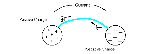 |
There is a force between them, the potential for work, and thus a voltage. Now we connect a conductor between them, a metal wire. On the positively charged sphere, positive charges rush along the wire to the other sphere, repelled by the nearby similar charges and attracted to the distant opposite charges. The same thing occurs on the other sphere and negative charge flows out on the wire. Positive and negative charges combine to neutralize each other, and the flow continues until there are no charge differences between any points of the entire connected system. There may be a net residual charge if the amounts of original positive and negative charge were not equal, but that charge will be distributed evenly so all the forces are balanced. If they were not, more charge would flow. The charge flow is driven by voltage or potential differences. After things have quieted down, there is no voltage difference between any two points of the system and no potential for work. All the work has been done by the moving charges heating up the wire.
The flow of charge is called electrical current. Current is measured in amperes (a), amps for short (named after another French scientist who worked mostly with magnetic effects). An ampere is defined as a flow of one Coulomb of charge in one second past some point. While a Coulomb is a lot of charge to have in one place, an ampere is a common amount of current; about one ampere flows through a 100 watt incandescent light bulb, and a stove burner or a large motor would require ten or more amperes. On the other hand low power digital circuits use only a fraction of an ampere, and so we often use units of of an ampere, a milliamp, abbreviated as ma, and even of a milliamp, or a microamp, . The currents on the RoboBoard are generally in the milliamp range, except for the motors, which can require a full ampere under heavy load. Current has a direction, and we define a positive current from point to as the flow of positive charges in the same direction. Negative charges can flow as well, in fact, most current is actually the result of negative charges moving. Negative charges flowing from to would be a negative current, but, and here is the tricky part, negative charges flowing from to would represent a positive current from to . The net effect is the same: positive charges flowing to neutralize negative charge or negative charges flowing to neutralize positive charge; in both cases the voltage is reduced and by the same amount.
Batteries Charges can be separated by several means to produce a voltage. A battery uses a chemical reaction to produce energy and separate opposite sign charges onto its two terminals. As the charge is drawn off by an external circuit, doing work and finally returning to the opposite terminal, more chemicals in the battery react to restore the charge difference and the voltage. The particular type of chemical reaction used determines the voltage of the battery, but for most commercial batteries the voltage is about 1.5 V per chemical section or cell. Batteries with higher voltages really contain multiple cells inside connected together in series. Now you know why there are 3 V, 6 V, 9 V, and 12 V batteries, but no 4 or 7 V batteries. The current a battery can supply depends on the speed of the chemical reaction supplying charge, which in turn often depends on the physical size of the cell and the surface area of the electrodes. The size of a battery also limits the amount of chemical reactants stored. During use, the chemical reactants are depleted and eventually the voltage drops and the current stops. Even with no current flow, the chemical reaction proceeds at a very slow rate (and there is some internal current flow), so a battery has a finite storage or shelf life, about a year or two in most cases. In some types of batteries, like the ones we use for the robot, the chemical reaction is reversible: applying an external voltage and forcing a current through the battery, which requires work, reverses the chemical reaction and restores most, but not all, the chemical reactants. This cycle can be repeated many times. Batteries are specified in terms of their terminal voltage, the maximum current they can deliver, and the total current capacity in ampere-hours.
You should handle batteries carefully, especially the ones we use in this course. Chemicals are a very efficient and compact way of storing energy. Just consider the power of gasoline or explosives, or the fact that you can play soccer for several hours powered only by a slice of cold pizza for breakfast. Never connect the terminals of a battery together with a wire or other good conductor. The battery we use for the RoboBoard is similar to the battery in cars, which uses lead and sulphuric acid as reactants. Such batteries can deliver very large currents through a short circuit, hundreds of amperes. The large current will heat the wire and possibly burn you; the resulting rapid internal chemical reactions also produce heat and the battery can explode, spreading nasty, reactive chemicals about. Charging these batteries with too large a current can have the same effect. Double check the circuit and instructions before connecting a battery to any circuit.
Circuit ElementsResistors
We need some way to control the flow of current from a voltage source, like a battery, so we do not melt wires and blow up batteries. If you think of current, charge flow, in terms of water flow, a good electrical conductor is like big water pipe. Water mains and fire hoses have their uses, but you do not want to take a drink from one. Rather, we use small pipes, valves, and other devices to limit water flow to practical levels. Resistors do the same for current; they resist the flow of charge; they are poor conductors. The value of a resistor is measured in ohms and represented by the Greek letter capital omega. There are many different ways to make a resistor. Some are just a coil of wire made of a material that is a poor conductor. The most common and inexpensive type is made from powdered carbon and a glue-like binder. Such carbon composition resistors usually have a brown cylindrical body with a wire lead on each end, and colored bands that indicate the value of the resistor. The key to reading these values is given in Chapter 2.
There are other types of resistors in your robot kit. The potentiometer is a variable resistor. When the knob of a potentiometer is turned, a slider moves along the resistance element. Potentiometers generally have three terminals, a common slider terminal, and one that exhibits increasing resistance and one that has decreasing resistance relative to the slider as the shaft is turned in one direction. The resistance between the two stationary contacts is, of course, fixed, and is the value specified for the potentiometer. The photoresistor or photocell is composed of a light sensitive material. When the photocell is exposed to more light, the resistance decreases. This type of resistor makes an excellent light sensor.
Ohm's LawOhm's law describes the relationship between voltage, , which is trying to force charge to flow, resistance, , which is resisting that flow, and the actual resulting current . The relationship is simple and very basic:  . Thus large voltages and/or low resistances produce large currents. Large resistors limit current to low values. Almost every circuit is more complicated than just a battery and a resistor, so which voltage does the formula refer to? It refers to the voltage across the resistor, the voltage between the two terminal wires. Looked at another way, that voltage is actually produced by the resistor. The resistor is restricting the flow of charge, slowing it down, and this creates a traffic jam on one side, forming an excess of charge with respect to the other side. Any such charge difference or separation results in a voltage between the two points, as explained above. Ohm's law tells us how to calculate that voltage if we know the resistor value and the current flow. This voltage drop is analogous to the drop in water pressure through a small pipe or small nozzle. . Thus large voltages and/or low resistances produce large currents. Large resistors limit current to low values. Almost every circuit is more complicated than just a battery and a resistor, so which voltage does the formula refer to? It refers to the voltage across the resistor, the voltage between the two terminal wires. Looked at another way, that voltage is actually produced by the resistor. The resistor is restricting the flow of charge, slowing it down, and this creates a traffic jam on one side, forming an excess of charge with respect to the other side. Any such charge difference or separation results in a voltage between the two points, as explained above. Ohm's law tells us how to calculate that voltage if we know the resistor value and the current flow. This voltage drop is analogous to the drop in water pressure through a small pipe or small nozzle.
Power Current flowing through a poor conductor produces heat by an effect similar to mechanical friction. That heat represents energy that comes from the charge traveling across the voltage difference. Remember that separated charges have the potential to do work and provide energy. The work involved in heating a resistor is not very useful, unless we are making a hotplate; rather it is a byproduct of restricting the current flow. Power is measured in units of watts (W), named after James Watt, the Englishman who invented the steam engine, a device for producing lots of useful power. The power that is released into the resistor as heat can be calculated as , where is the current flowing through the resistor and is the voltage across it. Ohm's law relates these two quantities, so we can also calculate the power as The power produced in a resistor raises its temperature and can change its value or destroy it. Most resistors are air-cooled and they are made with different power handling capacity. The most common values are 1/8, 1/4, 1, and 2 watt resistors, and the bigger the wattage rating, the bigger the resistor physically. Some high power applications use special water cooled resistors. Most of the resistors on the RoboBoard are 1/8 watt. The power produced in a resistor raises its temperature and can change its value or destroy it. Most resistors are air-cooled and they are made with different power handling capacity. The most common values are 1/8, 1/4, 1, and 2 watt resistors, and the bigger the wattage rating, the bigger the resistor physically. Some high power applications use special water cooled resistors. Most of the resistors on the RoboBoard are 1/8 watt.
Combinations of Resistors
Resistors are often connected together in a circuit, so it is necessary to know how to determine the resistance of a combination of two or more resistors. There are two basic ways in which resistors can be connected: in series and in parallel. A simple series resistance circuit is shown in Figure 4.4.
Figure 4.4: Two Resistors in Series
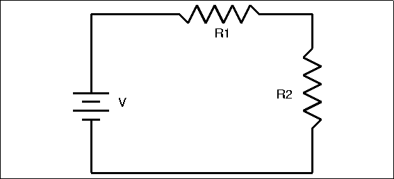 |
Determining the total resistance for two or more resistors in series is very simple. Total resistance equals the sum of the individual resistances. In this case, T=R1+R2 . This makes common sense; if you think again in terms of water flow, a series of obstructions in a pipe add up to slow the flow more than any one. The resistance of a series combination is always greater than any of the individual resistors.
The other method of connecting resistors is shown in Figure 4.5, which shows a simple parallel resistance circuit.
Figure 4.5: Two Resistors in Parallel
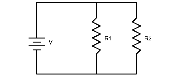 |
Our water pipe analogy indicates that it should be easier for current to flow through this multiplicity of paths, even easier than it would be to flow through any single path. Thus, we expect a parallel combination of resistors to have less resistance than any one of the resistors. Some of the total current will flow through R1 and some will flow through R2, causing an equal voltage drop across each resistor. More current, however, will flow through the path of least resistance. The formula for total resistance in a parallel circuit is more complex than for a series circuit:
| T={1{1R1}+{1R2}...+{1Rn}} | (1) |
Parallel and series circuits can be combined to make more complex structures, but the resulting complex resistor circuits can be broken down and analyzed in terms of simple series or parallel circuits. Why would you want to use such combinations? There are several reasons; you might use a combination to get a value of resistance that you needed but did not have in a single resistor. Resistors have a maximum voltage rating, so a series of resistors might be used across a high voltage. Also, several low power resistors can be combined to handle higher power. What type of connection would you use?
Capacitors are another element used to control the flow of charge in a circuit. The name derives from their capacity to store charge, rather like a small battery. Capacitors consist of two conducting surfaces separated by an insulator; a wire lead is connected to each surface. You can imagine a capacitor as two large metal plates separated by air, although in reality they usually consist of thin metal foils or films separated by plastic film or another solid insulator, and rolled up in a compact package. Consider connecting a capacitor across a battery, as in Fig. 4.6.
Figure 4.6: A simple capacitor connected to a battery through a resistor.
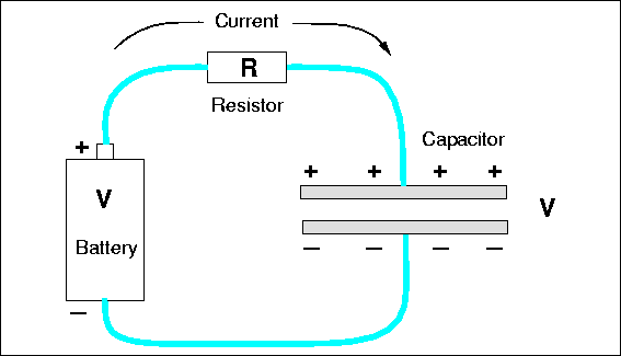 |
As soon as the connection is made charge flows from the battery terminals, along the wire and onto the plates, positive charge on one plate, negative charge on the other. Why? The like-sign charges on each terminal want to get away from each other. In addition to that repulsion, there is an attraction to the opposite-sign charge on the other nearby plate. Initially the current is large, because in a sense the charges can not tell immediately that the wire does not really go anywhere, that there is no complete circuit of wire. The initial current is limited by the resistance of the wires, or perhaps by a real resistor, as we have shown in Fig. 4.6. But as charge builds up on the plates, charge repulsion resists the flow of more charge and the current is reduced. Eventually, the repulsive force from charge on the plate is strong enough to balance the force from charge on the battery terminal, and all current stops. Figure 4.7 shows how the current might vary with
Figure 4.7: The time dependence of the current in the circuit of Fig. 4.6 for two values of resistance.
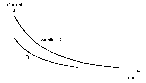 |
time for two different values of resistors. For a large resistor, the whole process is slowed because the current is less, but in the end, the same amount of charge must exist on the capacitor plates in both cases. The magnitude of the charge on each plate is equal.
The existence of the separated charges on the plates means there must be a voltage between the plates, and this voltage be equal to the battery voltage when all current stops. After all, since the points are connected by conductors, they should have the same voltage; even if there is a resistor in the circuit, there is no voltage across the resistor if the current is zero, according to Ohm's law. The amount of charge that collects on the plates to produce the voltage is a measure of the value of the capacitor, its capacitance, measured in farads (f). The relationship is , where Q is the charge in Coulombs. Large capacitors have plates with a large area to hold lots of charge, separated by a small distance, which implies a small voltage. A one farad capacitor is extremely large, and generally we deal with microfarads ( �f ), one millionth of a farad, or picofarads (pf), one trillionth -12) of a farad.
Consider the circuit of Fig. 4.6 again. Suppose we cut the wires after all current has stopped flowing. The charge on the plates is now trapped, so there is still a voltage between the terminal wires. The charged capacitor looks somewhat like a battery now. If we connected a resistor across it, current would flow as the positive and negative charges raced to neutralize each other. Unlike a battery, there is no mechanism to replace the charge on the plates removed by the current, so the voltage drops, the current drops, and finally there is no net charge left and no voltage differences anywhere in the circuit. The behavior in time of the current, the charge on the plates, and the voltage looks just like the graph in Fig. 4.7. This curve is an exponential function: . The voltage, current, and charge fall to about 37% of their starting values in a time of seconds, which is called the characteristic time or the time constant of the circuit. The time constant is a measure of how fast the circuit can respond to changes in conditions, such as attaching the battery across the uncharged capacitor or attaching a resistor across the charged capacitor. The voltage across a capacitor cannot change immediately; it takes time for the charge to flow, especially if a large resistor is opposing that flow. Thus, capacitors are used in a circuit to damp out rapid changes of voltage.
Combinations of Capacitors Like resistors, capacitors can be joined together in two basic ways: parallel and series. It should be obvious from the physical construction of capacitors that connecting two together in parallel results in a bigger capacitance value. A parallel connection results in bigger capacitor plate area, which means they can hold more charge for the same voltage. Thus, the formula for total capacitance in a parallel circuit is:
the same form of equation for resistors in series, which can be confusing unless you think about the physics of what is happening.
The capacitance of a series connection is lower than any capacitor because for a given voltage across the entire group, there will be less charge on each plate. The total capacitance in a series circuit is
| T={1{1C1}+{1C2}...+{1Cn}}. | (3) |
Again, this is easy to confuse with the formula for parallel resistors, but there is a nice symmetry here.
Inductors Inductors are the third and final type of basic circuit component. An inductor is a coil of wire with many windings, often wound around a core made of a magnetic material, like iron. The properties of inductors derive from a different type of force than the one we invented charge to explain: magnetic force rather than electric force. When current flows through a coil (or any wire) it produces a magnetic field in the space outside the wire, and the coil acts just like any natural, permanent magnet, attracting iron and other magnets. If you move a wire through a magnetic field, a current will be generated in the wire and will flow through the associated circuit. It takes energy to move the wire through the field, and that mechanical energy is transformed to electrical energy. This is how an electrical generator works. If the current through a coil is stopped, the magnetic field must also disappear, but it cannot do so immediately. The field represents stored energy and that energy must go somewhere. The field contracts toward the coil, and the effect of the field moving through the wire of the coil is the same as moving a wire through a stationary field: a current is generated in the coil. This induced current acts to keep the current flowing in the coil; the induced current opposes any change, an increase or a decrease, in the current through the inductor. Inductors are used in circuits to smooth the flow of current and prevent any rapid changes.
The current in an inductor is analogous to the voltage across a capacitor. It takes time to change the voltage across a capacitor, and if you try, a large current flows initially. Similarly, it takes time to change the current through an inductor, and if you insist, say by opening a switch, a large voltage will be produced across the inductor as it tries to force current to flow. Such induced voltages can be very large and can damage other circuit components, so it is common to connect some element, like a resistor or even a capacitor across the inductor to provide a current path and absorb the induced voltage. (Often, a diode, which we will discuss later, is used.)
Inductors are measured in henrys (h), another very big unit, so you are more likely to see millihenries, and microhenries. There are almost no inductors on the RoboBoard, but you will be using some indirectly: the motors act like inductors in many ways. In a sense an electric motor is the opposite of an electrical generator. If current flows through a wire that is in a magnetic field (produced either by a permanent magnet or current flowing through a coil), a mechanical force will be generated on the wire. That force can do work. In a motor, the wire that moves through the field and experiences the force is also in the form of a coil of wire, connected mechanically to the shaft of the motor. This coil looks like and acts like an inductor; if you turn off the current (to stop the motor), the coil will still be moving through the magnetic field, and the motor now looks like a generator and can produce a large voltage. The resulting inductive voltage spike can damage components, such as the circuit that controls the motor current. In the past this effect destroyed a lot of motor controller chips and other RoboBoard components. The present board design contains special diodes that will withstand and safely dissipate the induced voltages -- we hope.
Combinations of InductorsYou already know how inductors act in combination because they act just like resistors. Inductance adds in series. This makes physical sense because two coils of wire connected in series just looks like a longer coil. Parallel connection reduces inductance because the current is split between the several coils and the fields in each are thus weaker.
Semiconductor Devices
The Truth About Charge Our statements above about charge are not wrong, but they are simple and incomplete. In order to understand how semiconductor devices work one needs a more complete description of the nature of charge in the real world. Charge does not exist independently; it is carried by subatomic particles. For this discussion we will be concerned primarily with electrons, which carry a negative charge of -19 C , the minimum amount of charge that can exist in isolation. At least, no one has found any smaller amount than this fundamental quantum of charge.
Electrons are one component of atoms and molecules. Atoms are the building blocks out of which all matter is constructed. Atoms bond with each other to form substances. Substances composed of just one type of atom are called elements. For example, copper, gold and silver are all elements; that is, each of them consists of only one type of atom. More complex substances are made up of more than one atom and are known as compounds. Water, which has both hydrogen and oxygen atoms, is such a compound. The smallest unit of a compound is a molecule. A water molecule, for example, contains two hydrogen atoms and one oxygen atom.
Atoms themselves are made up of even smaller components: protons, neutrons and electrons. Protons and neutrons form the nucleus of an atom, while the electrons orbit the nucleus. Protons carry positive charge and electrons carry negative charge; the magnitude of the charge for both particles is the same, one quantum charge, -19 C . Neutrons are not charged. Normally, atoms have the same number of protons and electrons and have no net electrical charge.
Figure 4.8: Structure of an Atom
 |
Electrons that are far from the nucleus are relatively free to move around under the influence of external fields because the force of attraction from the positive charge in the nucleus is weak at large distances. In fact, it takes little force in many cases to completely remove an outer electron from an atom, leaving an ion with a net positive charge. Once free, electrons can move at speeds approaching the speed of light (roughly 670 million miles per hour) through metals, gases and vacuum. They can also become attached to another atom, forming an ion with net negative charge.
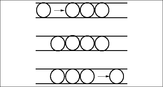
Electric current in metal conductors consists of a flow of free electrons. Because electrons have negative charge, the flow of electrons is in a direction opposite to the positive current. Free electrons traveling through a conductor drift until they hit other electrons attached to atoms. These electrons are then dislodged from their orbits and replaced by the formerly free electrons. The newly freed electrons then start the process anew. At the microscopic level, electron flow through a conductor is not a steady stream, like water flowing from a faucet, but rather a series of short bursts.
Figure 4.9: A Simple Model of Electron Flow
 |
Silicon
Semiconductor devices are made primarily of silicon (silicon's element symbol is "Si"). Pure silicon forms rigid crystals because of its four valence (outermost) electron structure -- one Si atom bonds to four other Si atoms forming a very regularly shaped diamond pattern. Figure 4.10 shows part of a silicon crystal structure.
Figure 4.10: A Silicon Crystal Structure
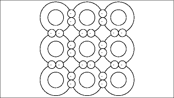 |
Pure silicon is not a conductor because there are no free electrons; all the electrons are tightly bound to neighboring atoms. To make silicon conducting, producers combine or "dope" pure silicon with very small amounts of other elements like boron or phosphorus. Phosphorus has five outer valence electrons. When three silicon atoms and one phosphorus atom bind together in the basic silicon crystal cell of four atoms, there is an extra electron and a net negative charge. Figure4.11 shows the crystal structure of phosphorus doped silicon.
Figure 4.11: Silicon Doped with Phosphorus
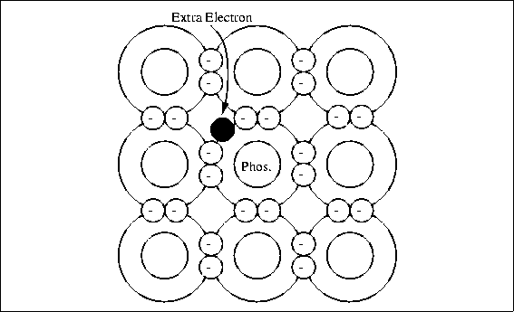 |
This type of material is called n-type silicon. The extra electron in the crystal cell is not strongly attached and can be released by normal thermal energy to carry current; the conductivity depends on the amount of phosphorus added to the silicon.
Boron has only three valance electrons. When three silicon atoms and one boron atom bind with each other there is a "hole" where another electron would be if the boron atom were silicon; see Fig. 4.12. This gives the crystal cell a positive net charge (referred to as p-type silicon), and the ability to pick up an electron easily from a neighboring cell.
Figure 4.12: Silicon Doped with Boron
 |
The resulting migration of electron vacancies or holes acts like a flow of positive charge through the crystal and can support a current. It is sometimes convenient to refer to this current as a flow of positive holes, but in fact the current is really the result of electrons moving in the opposite direction from vacancy to vacancy.
Diodes Both p-type and n-type silicon will conduct electricity just like any conductor; however, if a piece of silicon is doped p-type in one section and n-type in an adjacent section, current will flow in only one direction across the junction between the two regions. This device is called a diode and is one of the most basic semiconductor devices.
A diode is called forward biased if it has a positive voltage across it from from the p- to n-type material. In this condition, the diode acts rather like a good conductor, and current can flow, as in Fig. 4.13.
Figure 4.13: A Forward Biased Diode
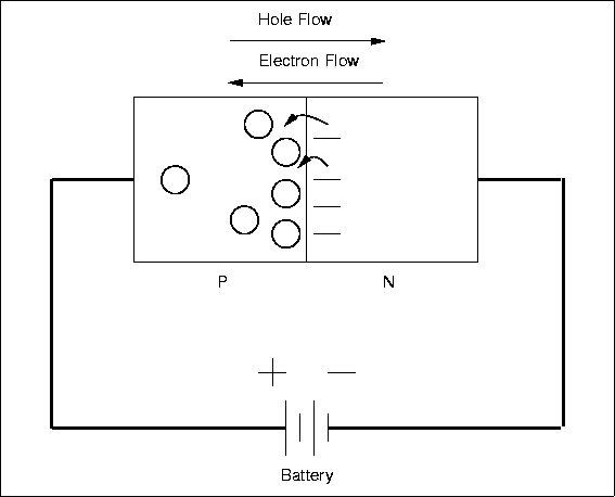 |
There will be a small voltage across the diode, about 0.6 volts for Si, and this voltage will be largely independent of the current, very different from a resistor.
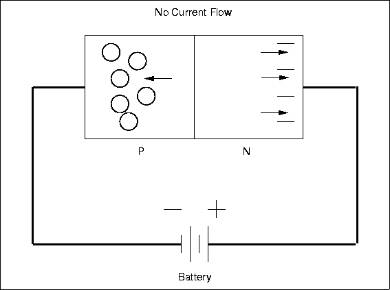
If the polarity of the applied voltage is reversed, then the diode will be reverse biased and will appear nonconducting (Fig. 4.14). Almost no current will flow and there will be a large voltage across the device.
Figure 4.14: A Reverse Biased Diode
 |
The non-symmetric behavior is due to the detailed properties of the pn-junction. The diode acts like a one-way valve for current and this is a very useful characteristic. One application is to convert alternating current (AC), which changes polarity periodically, into direct current (DC), which always has the same polarity. Normal household power is AC while batteries provide DC, and converting from AC to DC is called rectification. Diodes are used so commonly for this purpose that they are sometimes called rectifiers, although there are other types of rectifying devices. Figure 4.15 shows the input and output current for a simple half-wave
Figure 4.15: A Half-Wave Rectifier
 |
rectifier. The circuits gets its name from the fact that the output is just the positive half of the input waveform. A full-wave rectifier circuit (shown in Figure 4.16) uses four diodes arranged so that both polarities of the input waveform can be used at the output.
Figure 4.16: A Full-Wave Rectifier
 |
The full-wave circuit is more efficient than the half-wave one.

 Subsections
 | The Microprocessor and Memory
 | Multiplexing Data and Address Signals |
|
 | Memory Mapping
 | Memory-Mapping the RAM |
 | Memory-Mapping with the PAL16L8 Chip |
 | System Memory Map |
 | Digital Inputs |
 | Digital Outputs |
 | 68HC11 and Memory Schematic |
|
 | The Motor Drivers
 | The H-Bridge Circuit |
 | The H-Bridge with Enable Circuitry |
 | The SGS Thompson L298N Motor Driver Chip |
 | Power Considerations
 | Current Handling and Spike Protection |
 | Power Supply Isolation |
|
|
 | Analog Inputs
 | Motor Current Monitoring Circuit |
 | Analog Input Multiplexing on the RoboBoard |
|
 | The Serial Line Circuit |
 | High Speed Serial Peripheral Interface
 | Introduction to the SPI |
 | RoboBoard SPI Configuration |
 | Suggested Protocols |
|
 | Non-Volatile Static RAM |
 | The Infrared Transmission Circuit
 | The IR Beacon |
|
 | The LCD Display |
ELEC 201 Hardware
This chapter is partly tutorial and partly technical reference: in additional to documenting the Rice ELEC 201 RoboBoard hardware, it explains the design in a way that assumes minimal background in digital electronics. Additional explanatory material can be found in the Glossary (Appendix B) and in Chapter 12.
The information presented here should be considered optional, as it is not strictly necessary to know it to build a robot. Hopefully though, this chapter will satisfy most readers' curiosity about how the ELEC 201 hardware works.
The Microprocessor and Memory At the most primitive level, a computer consists of a microprocessor, which executes instructions, and a memory, for storing those instructions (as well as other data).
Figure 5.1: Diagram of Microprocessor and Memory
Figure 5.1 is a block diagram of the microprocessor and memory, showing four types of wires that connect the two:
- Address Bus.
- These wires are controlled by the microprocessor to select a particular location in memory for reading or writing. The RoboBoard uses a memory chip that has 15 address wires. Since each wire has two states (it can be a digital one or a zero), 2 to the 15th power locations are possible. 215 is precisely 32,768 locations; thus, the system is said to have "32K" of memory (1K = 1024 bytes).
-
- Data Bus.
- These wires are used to pass data between the microprocessor and the memory. When data is written to the memory, the microprocessor drives the data bus; when data is read from the memory, memory drives the bus.In our example (and in the RoboBoard), there are eight data wires (or bits). These wires can transfer one of 8 , or 256, different values per transaction. The data size of 8 bits is commonly referred to as abyte. (This jargon gets worse; a data size of 4 bits is frequently referred to as a nybble.)
- Read/Write Control Line.
- This single wire is driven by the microprocessor to control the function of the memory. If the read/write control line is asserted as a logical one, i.e., ``true'', then the memory performs a ``read'' operation. If it is asserted as a logic zero, i.e., ``false'' then the memory performs a ``write'' operation. (The relationship between logic level and voltage level can vary, depending on the implementation. For example, with the exception of some of the serial port circuitry, a logical ``zero'' on the RoboBoard corresponds to a voltage level near 0 volts, and a logical ``one'' on the RoboBoard corresponds to a voltage level near 5 volts.)
-
- Memory Enable Control Line.
- This wire, also called the E clock, connects to the enable circuitry of the memory. When the memory is enabled, it performs either a read or write operation as determined by the read/write line.
Multiplexing Data and Address Signals Figure 5.2: Block Diagram of Microprocessor and Memory with Latch Memory Mapping
Figure 5.3: RoboBoard System Block Diagram
|
So far we have seen how a memory can be connected to the address space of a microprocessor. In a circuit like the one of the RoboBoard, the microprocessor must interact with other devices besides the memory -- for example, motors and sensors. A typical solution uses 8-bit latches for input and output. These latches are connected to the data bus of the microprocessor so that they appear like a location in memory. Then, the act of reading or writing from one of these memory locations causes data to be read from or written to a latch -- to which the external devices are connected. Figure 5.3 is a block diagram of the ELEC 201 RoboBoard system. Notice that chips marked "574" are connected to the data bus. The '574s have outputs that control the motors (through other chips marked "L298N", which will be discussed later). The digital sensors are driven onto the data bus by a chip marked "245." Another '574 chip is used for eight bits of digital output. These interface chips are used in a technique called memory mapping. The chips are "mapped" to a particular address in the microprocessor's memory. The following discussion will show how both the 32K RAM memory and the digital input and output interface chips share the address space of the microprocessor. Memory-Mapping the RAM
Figure 5.4: Enabling the Memory
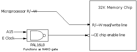 |
The 68HC11 has a total of 16 address bits, yielding 65536 ("64K") bytes of addressable locations. Half of this space will be taken up by the 32K memory chip (also known as a RAM chip, for "Random Access Memory"). The 68HC11 has a bank of interrupt vectors, which are hardware-defined locations in the address space where the microprocessor expects to find pointers to driver routines. When the microprocessor is reset, it finds the reset vector to determine where it should begin running a program. These vectors are located in the upper 32K of the address space. Thus, it is logical to map the RAM into this upper block, so that the RAM may be used to store these vectors. The technique used to map the memory to the upper 32K block is fairly simple. Whenever the 68HC11's A15 (the highest-order address bit) is logic one, an address in the upper 32K is being selected. The other fifteen address bits (A0 through A14) determine the address within that 32K. A logic gate (actually a portion of a programmable logic device called a "PAL") is used to enable the memory when A15 is logic one and when the E clock is high (since the E clock must control the timing of the enable). Figure 5.4 shows a block diagram of this circuit. Memory chips are part of a class of chips that have active low (sometimes called "active false") enable inputs, meaning that they are enabled when the enable input is logic zero, not logic one. There are two methods for denoting an input that is active low. As shown in Figure 5.4, the chip enable input is shown with connecting to a circle; this circle indicates an active low input. Also, the name for the signal, CE is prefixed with a ~ symbol. The NAND gate shown in Figure 5.4 actually combines two logic functions, a NOT gate (inverter), and an AND gate. The function of the NOT gate is to convert the active-high enable produced by the AND gate into the active low signal required by the ~CE input. Memory-Mapping with the PAL16L8 Chip
Figure 5.5: Typical 3-to-8 74x138 Address Decoder
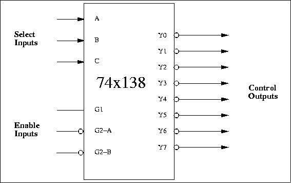 |
Most computers use a circuit called an address decoder to demultiplex address lines and generate memory-mapped control enables for individual devices. Figure 5.5 shows the logical diagram of a 74x138 demultiplexer, which is commonly used in circuits that map devices onto an address space. This chip is a 3-to-8 decoder: a binary number of three digits (the select inputs) causes one of eight possible outputs to be selected (the control outputs). The chip also has three enable inputs, all of which must be enabled to make the chip become active. Previous versions of the RoboBoard used a 74AC138 for address decoding. Versions 3.0 and later of the RoboBoard implement this functionality using a PAL16L8 programmable logic device. The behavior of this device is controlled by "PAL code", which is shown in Figure 5.7
Figure 5.6: Wiring the PAL16L8 Address Decoder
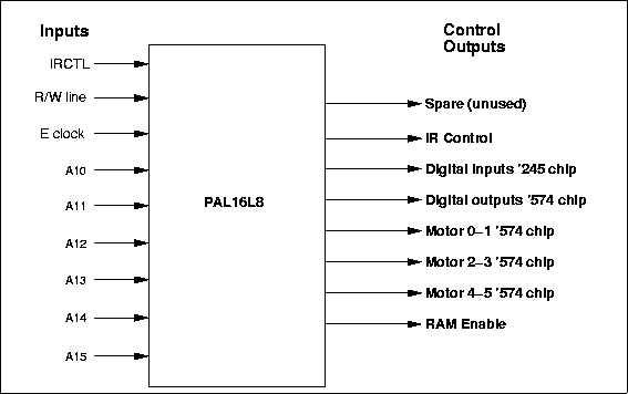 |
Figure 5.7: PAL16L8 ABEL Code
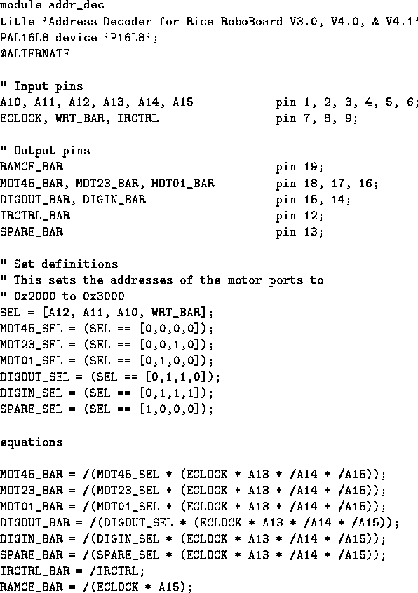 |
Examining the PAL code (written in a language called "ABEL"), we see that the outputs of the PAL16L8 control the input and output latches shown in the system block diagram. The PAL16L8 determines when these latches are activated, either to read data from the data bus (in the case of the '574 output latch), or to write data onto the data bus (in the case of the '245 input buffer). As determined by the PAL code, the inputs of the PAL16L8 determine when the outputs will become active, and thereby turn on one, and only one, of the control outputs. This is to avoid the possibility that two devices (the RAM and perhaps the '245) would attempt to drive the data bus simultaneously, causing a problematic situation called bus contention. System Memory Map Figure 5.8 summarizes the memory map solution that has been implemented for the ELEC 201 RoboBoard.
Figure 5.8: RoboBoard 68HC11 System Memory Map
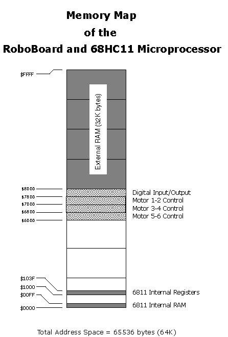 |
The 32K RAM takes up half of the total address space of the microprocessor. As indicated in the map, it is located in the upper 32K of the microprocessor's memory, from addresses $8000 to $FFFF. The digital output and input ports are mapped at location $7800. The three motor control ports are mapped at locations $7000 (motors 1 and 2), $6800 (motors 3 and 4), and $6000 (motors 5 and 6). There is a small area of memory that is internal to the 68HC11 chip itself. This memory consists of 256 bytes located at the start of the address space, from locations $00 to $FF. The 68HC11 also has a bank of 64 internal special function registers, located at addresses $1000 to $103F. These registers control various hardware features of the 68HC11 (the analog inputs and serial communications are two examples). The remainder of this section presents details on the digital input and output circuit wiring. Digital Inputs
Figure 5.9: Digital Input Circuit
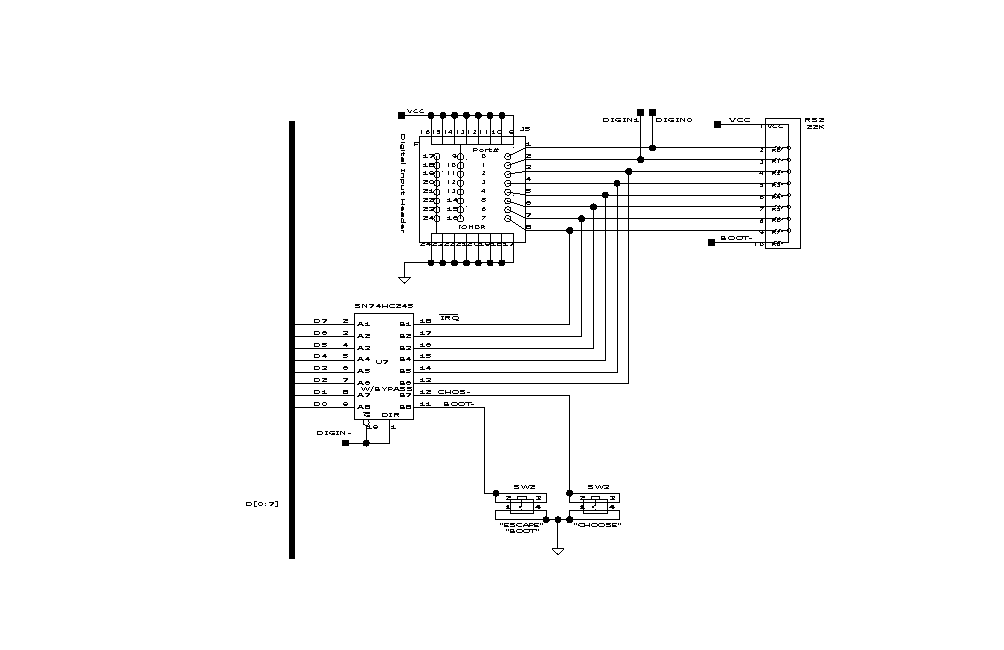 |
Figure 5.9 shows the digital input circuitry. U7, a 74HC245 chip, is used to buffer an eight-bit word of sensor inputs and drive the 68HC11 data bus with that value when the chip is selected. The '245 is actually a bi-directional buffer or transceiver, but we connect the direction select to the enable so that the '245 can only serve as an input device. The lower two bits of the '245 are connected to the two user buttons (that have been dubbed CHOOSE and ESCAPE). The upper six bits are connected to the digital input header. The lower two bits of the input header are connected to two timer inputs of the 68HC11. These inputs can be used to precisely measure waveforms, or can simply be used for digital input. The library functions written to perform digital inputs insulate the user from the fact that the eight pins on the input header are not mapped contiguously to one location in memory. RS2, a 22K resistor pack, contains pull-up resistors for the inputs of the '245 chip, making the default value of the inputs a logical one. One of the digital inputs (pin 8 of the Digital Input Header) is also tied to one of the 68HC11's external interrupt lines (IRQ, the maskable interrupt). This input is normally pulled high, leaving the interrupt inactive when no input is connected. The default interrupt handler routine simply returns when it is called, so no software modifications need to be made if the input is used as a digital I/O line. However, the simple act of acknowledging and returning from an interrupt takes some time, during which the processor cannot perform other functions. Therefore, frequently changing inputs should not be connected to this digital input. A user defined interrupt routine can be installed if the signal is to be used as an interrupt. Digital Outputs Figure 5.15 shows the complete schematic for the three '574 output latches controlling the motors. Notice that the data inputs of the '574s are connected to the 68HC11 data bus. The MOT01, MOT23, and MOT45 control signals connect to the clock inputs of the three '574s; when one of these is activated, the corresponding '574 latches the value present on the data bus. The outputs of the '574 connect to the motor driver chips, the circuitry of which is explained in the following section. 68HC11 and Memory Schematic Figure 5.10 presents the schematic of the 68HC11, memory, address decoding, and supporting main circuitry on the ELEC 201 Processor Board. By the end of this chapter, most of the circuitry depicted here will be explained.
Figure 5.10: 68HC11, Memory, Address Decoding and Miscellaneous Circuitry
|
The Motor Drivers Motors are high-powered devices in the world of digital electronics. A typical digital output can supply about 10 to 20 milliamperes (mA) of current; a small permanent-magnet motor requires anywhere from 500 to 4000 mA of current. Special circuits are therefore required to drive motors. The H-Bridge Circuit
Figure 5.11: The H-Bridge Circuit
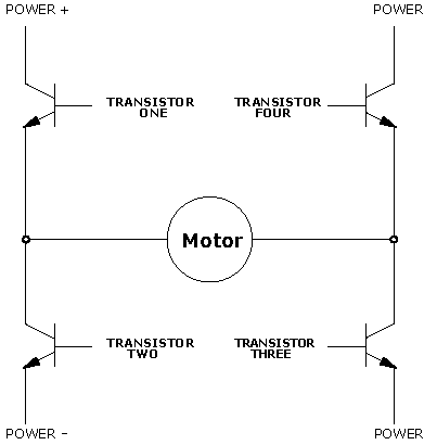 |
A circuit known as the H-bridge (named for its topological similarity to the letter "H") is commonly used to drive motors. In this circuit (depicted in Figure 5.11), two of four transistors are selectively enabled to control current flow through a motor.
Figure 5.12: The H-Bridge with Left-to-Right Current Flow
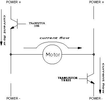 |
As shown in Figure 5.12, an opposite pair of transistors (Transistor One and Transistor Three) is enabled, allowing current to flow through the motor. The other pair is disabled, and can be thought of as out of the circuit. By determining which pair of transistors is enabled, current can be made to flow in either of the two directions through the motor. Because permanent-magnet motors reverse their direction of turn when the current flow is reversed, this circuit allows bidirectional control of the motor. The H-Bridge with Enable Circuitry
Figure 5.13: The H-Bridge with Enable Circuitry
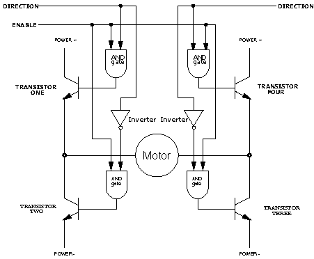 |
It should be clear that one would never want to enable Transistors One and Two or Transistors Three and Four simultaneously. This would cause current to flow from Power + to Power - through the transistors, and not the motors, at the maximum current-handling capacity of either the power supply or the transistors. This usually results in failure of the H-Bridge. To prevent the possibility of this failure, enable circuitry as depicted in Figure 5.13 is typically used. In this circuit, the internal inverters ensure that the vertical pairs of transistors are never enabled simultaneously. The Enable input determines whether or not the whole circuit is operational. If this input is false, then none of the transistors are enabled, and the motor is free to coast to a stop. By turning on the Enable input and controlling the two Direction inputs, the motor can be made to turn in either direction. Note that if both direction inputs are the same state (either true or false) and the circuit is enabled, both terminals will be brought to the same voltage (Power + or Power - , respectively). This operation will actively brake the motor, due to a property of motors known as back emf, in which a motor that is turning generates a voltage counter to its rotation. When both terminals of the motor are brought to the same electrical potential, the back emf causes resistance to the motor's rotation. The SGS Thompson L298N Motor Driver Chip
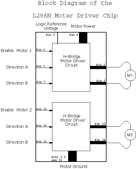
Figure 5.14: The SGS Thompson L298N Motor Driver IC
 |
The SGS Thompson L298N 8 motor control chip incorporates two H-bridge motor-driving circuits into a single 15-pin package. Figure 5.14 shows a block diagram of this useful integrated circuit. The schematic of the motor circuit (Figure 5.15) shows how the L298N chips are controlled in the ELEC 201 RoboBoard design. Six bits are used to control two motors. Four of the bits determine the direction of the motors and two bits determine when the motors are on or off. There are three such circuits on the RoboBoard, one for each pair of motors. The remaining two bits of each of the '574 chips are available as extra digital outputs, two of which are connected to transistor drivers. These transistor circuits are well-suited for powering light-load devices, such as LEDs or small lights. The other four outputs are routed to an output header. The speed of a motor may be controlled by pulsing the enable bit of its associated controller chip on and off. This technique, called pulse width modulation, is explained in the chapter on motors.
Figure 5.15: Motor and LED Driver Circuit
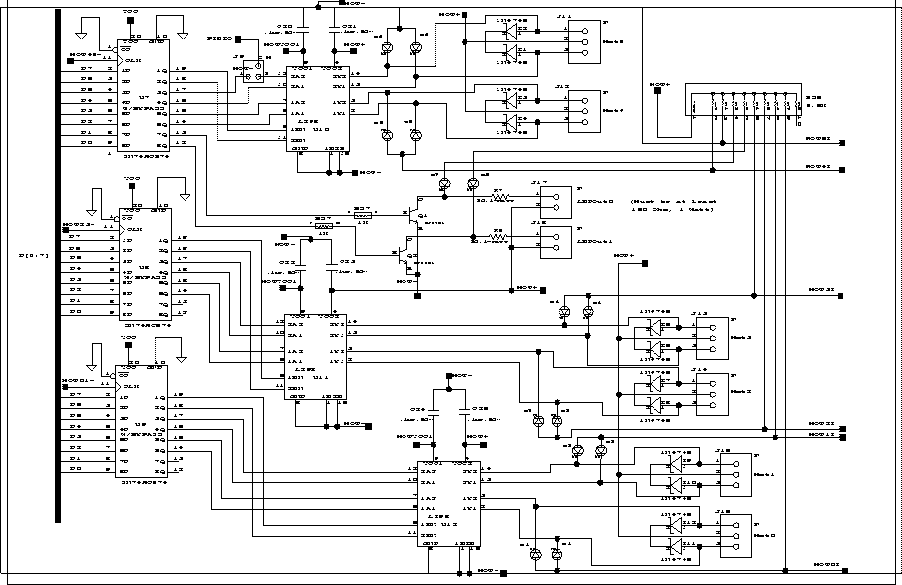 |
Power ConsiderationsCurrent Handling and Spike Protection The L298N does not have significant internal protection against spike and other electrical noise. Therefore, diodes and capacitors have been added to the motor control circuitry as shown in Figure 5.15. These diodes and capacitors protect the motor chip and the rest of the circuit from electrical noise (inductive spikes) generated by the motors. The L298N can supply 2000 mA of current per motor. Since the stall current (the current drawn by the motor when the shaft is unable to turn) of the motors used in ELEC 201 is less than 1500 mA, the L298N circuit is adequate for our purposes. Power Supply Isolation Electrical noise generated by motors can be hazardous to a microprocessor circuit even with the use of the diodes. Therefore the motors use separate power circuitry and filtering from the rest of the microprocessor electronics.
Figure 5.16: Power Supply and Regulating Circuit
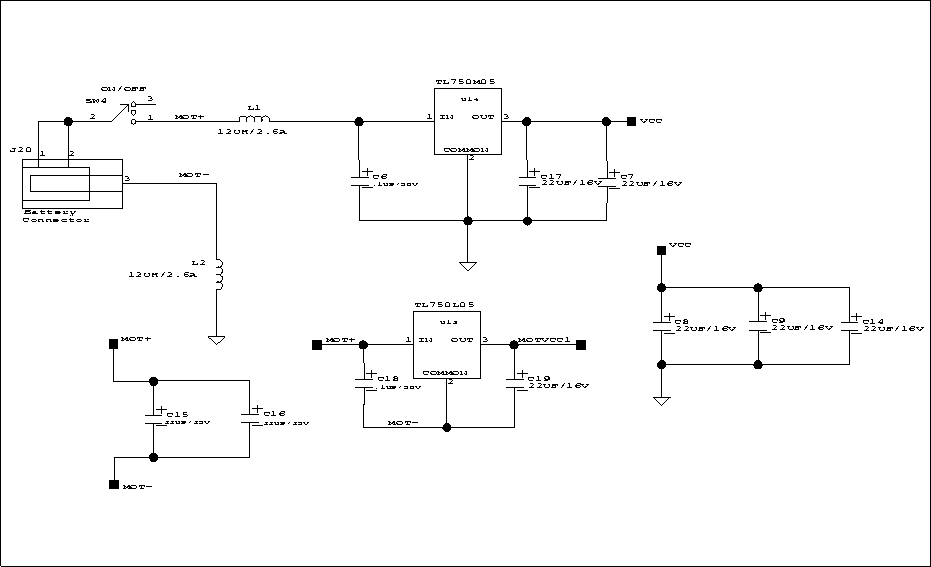 |
Figure 5.16 shows the power-supply circuitry. Logic power (VCC), the supply voltage for the microprocessor circuitry, is provided by a TL750M05 low-dropout 5-Volt voltage regulator, while Motor power for the motors is supplied directly from the battery. The control circuits of the L298N motor drivers also require a small amount of logic power; this is provided by a separate TL750L05 5-Volt regulator, as shown in Figure 5.16. The motor ground and the logic ground must be kept at the same potential so that the control signals from the '574 chip shown in Figure 5.15 can communicate with the L298N chips. These grounds are kept at the same potential by the inductor L2. Inductor L2 prevents motor current surges from upsetting the microprocessor power supply. The inductors provide reactance (frequency-dependent resistance) to trap electrical noise that might travel from the motors, through the L298N chips, and into the microprocessor circuit. Analog Inputs The 68HC11 has on-chip circuitry to perform an analog-to-digital signal conversion. In this operation, a voltage from 0 to 5 volts is converted into an 8-bit number (a range of 0 to 255, where zero volts corresponds with 0, and 5 volts with 255). This conversion feature is one of many that make the 68HC11 well-suited for control applications. The 68HC11 has eight of these analog inputs. In the ELEC 201 RoboBoard design, six of these pins are wired to a motor current monitoring circuit, and two of them are wired to analog multiplexors, as described below. Motor Current Monitoring Circuit When the L298N chips drive a motor, there is a voltage drop across the transistors that form the H-bridge. The transistor connected to motor ground (0 volt potential) might drive the motor at some voltage between .2 and .8 volts; the transistor connected to the positive terminal of the battery (say it is at 12 volts) might drive the motor between 11.2 and 11.8 volts. The amount of this voltage drop is proportional to the amount of current being supplied by the motor-driving transistor. The greater the supply of current, the greater the voltage drop across the transistor. This somewhat undesirable property of the L298N transistors is exploited to give a crude measurement of the amount of current being driven through the motor. A fundamental property of motors is that, as the amount of work they are performing increases, the amount of current they draw also increases. So the current measurement yields data on how hard the motor is working -- if it is turning freely, if it is stalled, or if it is working somewhere in between. As indicated in Figure 5.15, the voltage feedback point is tapped from the indicator LEDs that are connected to the motor outputs. The voltage across the LEDs will decrease as a result of increased current draw of the motor (and the corresponding decreased performance of the L298Ns). This voltage is fed to a 68HC11 analog input and can be measured by the 68HC11 analog-to-digital conversion hardware. Each of the six motor circuits is wired in this way to a 68HC11 analog input. Analog Input Multiplexing on the RoboBoard
Figure 5.17: Analog Input and Digital Output Circuitry
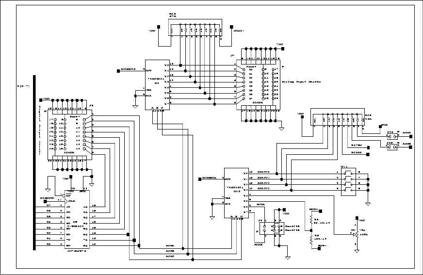 |
The RoboBoard has two eight-to-one analog multiplexor ICs. These chips (the 74HC4051) have eight inputs and one output; depending on the state of three selector inputs, one of the eight input lines is connected to the output. (Actually, the chip's signals are bidirectional, but for the purpose of this discussion, it is convenient to think of the chip as having eight inputs and one output.) The outputs of the two '4051 chips are wired into the 68HC11 analog inputs. Three signals from the 68HC11 are used to control the multiplexers and select which analog input is mapped to the 68HC11 analog input. These signals are taken from the three low order bits of the digital output port. Figure 5.17 is a schematic of the analog input circuitry on the ELEC 201 RoboBoard. It is easy to see how the use of the analog multiplexor chips greatly expands the analog input capability of the ELEC 201 hardware:
 | The inputs of one of the '4051 chips are wired to a bank of eight analog-sensor inputs. |
 | The other '4051 chip is connected to the RoboKnob, a general-purpose analog input controlled by a variable resistor, four DIP switches (for user configuration input), and a voltage divider that allows the battery voltage to be directly measured. |
 | Two of the inputs to this second chip are available as general purpose analog inputs. |
The Serial Line Circuit
Figure 5.18: Host and Board Communications over 3-Wire Serial Link
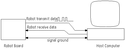 |
The ELEC 201 Board communicates with a host computer over an RS-232 serial line. "RS-232" refers to a standard protocol for communications over a three-wire system, as depicted in Figure 5.18. Nearly all of today's computers have serial ports that conform to the RS-232 standard.* *The actual RS-232 standard involves quite a few more wires for conveying various status information, but the data itself is transmitted on two uni-directional wires In the RS-232 system, a "logic zero" is indicated by a 10 volt signal with respect to ground, and a "logic one" is indicated by a 10 volt signal. Note that this is different from standard digital logic levels in several ways. Negative voltages are used, higher voltages are used, and negative voltages connote a logic one value. The 68HC11 chip includes circuitry to generate waveforms compatible with the RS-232 systems, but requires external circuitry to convert its own signals, which obey the digital logic norms, to RS-232 signals as described.
Figure 5.19: Serial Line Circuit
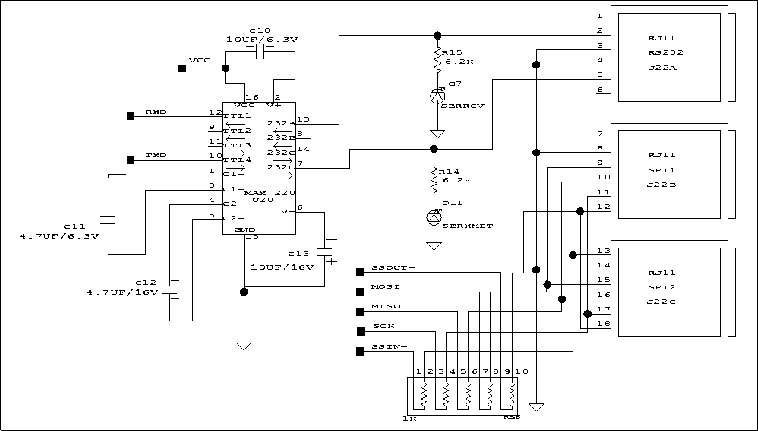 |
U20, in Figure 5.19, is used to convert between the RS-232 voltage levels, and the digital logic voltage levels used everywhere else on the RoboBoard. This circuit contains two charge pumps to generate the negative voltages that are required. The first is used to double the system voltage of 5 volts to obtain a 10 volt supply that more closely matches the RS-232 standard. The second charge pump inverts this 10 volts to obtain a 10 volt supply. High Speed Serial Peripheral Interface The Serial Peripheral Interface (SPI) circuit is a synchronous serial data link that is standard across many Motorola microprocessors and other peripheral chips. It provides support for a high bandwidth (1 megabit) network connection between CPUs and other devices supporting the SPI. The RoboBoard's two SPI network jacks allow multiple RoboBoards or other SPI devices to be connected using a six-wire RJ-11 (telephone jack) connection. This six-wire RJ-11 interface is downward compatible with the four-wire SPI interface found on the M.I.T. "Mini Board". The RoboBoard uses a particular configuration of the SPI system that requires a minimum of external hardware support. Multiple RoboBoards may be networked with no additional components other than the cabling itself. A brief review of the SPI system follows, along with a discussion of the particular configuration of the SPI on the RoboBoard. Further details can be found in the Motorola M68HC11 Reference Manual. Introduction to the SPIThe Serial Peripheral Interface is essentially a shift register that serially transmits data bits to other SPIs. During a data transfer, one SPI system acts as the "master" that controls the data flow, while the other system acts as the "slave" that has data shifted into and out of it by the master. Different CPUs can take turns being master, and one master may simultaneously shift data into multiple slaves. However, only one slave may drive its output to write data back to the master at any given time. The basic SPI interface consists of two data lines and two control lines:
- Master Out Slave In
- Abbreviated MOSI, this data line supplies the output data from the master that is shifted into the input(s) of the slave(s).
- Master In Slave Out
- Abbreviated MISO, this data line supplies the output data from the master that is shifted into the input(s) of the slave(s).
- Serial Clock
- Abbreviated SCK, this control line is driven by the master that regulates the flow of the data bits. The master may transmit data at a variety of baud rates; the SCK line cycles once for each bit that is transmitted.
- Slave Select
- Abbreviated SS, this control line allows slaves to be turned on and off with hardware control.
RoboBoard SPI Configuration
Figure 5.20: Serial Peripheral Interface Jack
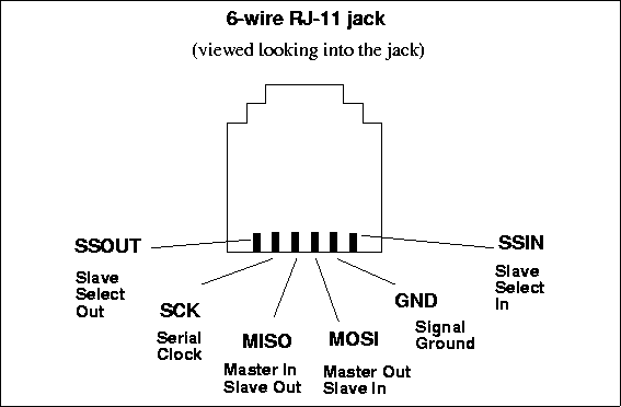 |
The RoboBoard uses a six-wire SPI connection that carries the MOSI, MISO, SCK, signal ground, and two lines that support the Slave Select function (see Figure 5.20). Slave Select Out is a digital output that is driven by bit 5 of Port A. Slave Select In to the 68HC11 is configured by J3 on the RoboBoard. If pins 1 and 3 are connected, Slave Select In is tied low (this is the Mini Board compatible configuration), if pins 2 and 3 are connected, Slave Select In is tied high, and if no jumper is installed in J3, Slave Select In will be at whatever level is present on the RJ-11 pin. In the Mini Board compatible configuration, software protocols must be used to enable the activity of the SPI slave. In the default configuration (no jumper in J3), multiple RoboBoards can be arranged in a "ring" topology, with mastership being passed around the ring by each RoboBoard controlling the Slave Select In of the downstream board.
To connect the SPI circuits of multiple RoboBoards, each respective line of each RoboBoard can be tied together: MOSI to MOSI, MISO to MISO, etc. To make this happen, the connecting RJ-11 cables must have half-twists in them. This configuration works because of the bi-directionality of each of the control lines. When a given SPI circuit is the master, it transmits on its MOSI line while slaves receive on their MOSI lines. Likewise a slave transmits on its MISO line and the master receives on its MISO line. The SCK line also is automatically configured properly (it is an output for the master and an input for the slave).
Suggested Protocols Two sample protocols are presented. The former, a single master protocol, would be significantly easier to implement than the latter, a multiple master protocol.
- Single Master Protocol.
- In this protocol, one CPU is always the master while all of the others are always slaves. One can imagine that the slave CPUs are simply input and output devices for the master. The master might desire to exchange information with a particular slave. To do this, the master would send a slave address datum in each communication packet. The selected slave would then enable its MISO line to write information back to the master. All other slaves would be required to turn their MISO lines off so as to not conflict with the selected slave. This protocol could be extended to allow the master to broadcast a message to multiple slaves, but only one slave may respond at a time (otherwise there would be hardware contention on the MISO).
- Multiple Master Protocol.
- This protocol allows CPUs to take turns being masters and request information from other CPUs at will. The trick here is to provide for some type of collision detection if more than one CPU decides to initiate a communication at the same time.
Non-Volatile Static RAM The static RAM used in the ELEC 201 board is a special device, manufactured by Dallas Semiconductor, that contains a 32K x 8 RAM, a small battery, and some circuitry that switches between normal and battery back-up power under controlled conditions. Having a battery-backed static memory greatly increases the usability of the ELEC 201 board, since a robot can simply be turned on and operated immediately, without having to be connected to a computer first. The Infrared Transmission Circuit
Figure 5.21: Square Wave Consisting of Bursts of 40 KHz Signals
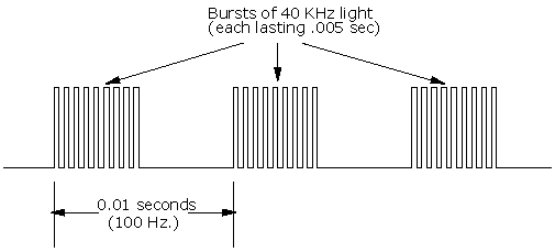 |
The Sharp GP1U52 sensor and others like it, commonly used in TVs, VCRs, and other devices controlled by infrared, is sensitive to modulated infrared light. It detects the presence of infrared light that is blinking on and off at a particular rate. The GP1U52 sensor is tuned to 40,000 Hertz (40 KHz). In TV remote applications, a data stream is then generated around the 40 KHz carrier frequency. The signal consists of bursts and gaps of the 40 KHz transmissions.
Figure 5.22: Sharp IR Sensor Decoding IR-Encoded Square Wave
 |
For the ELEC 201 application, the 40 KHz carrier is used to transmit a square wave of relatively low frequency (100 or 125 Hz), as shown in Figure 5.21. When the Sharp IR sensor decodes this signal, it removes the 40 KHz carrier, yielding a copy of the square wave that was originally transmitted (Figure 5.22). The ELEC 201 system software continuously checks the Sharp sensors for square waves of the specified frequency. The software actually locks on to the square wave when it is present and then counts the number of consecutive cycles that have been detected.
Figure 5.23: Block Diagram of Infrared Circuitry
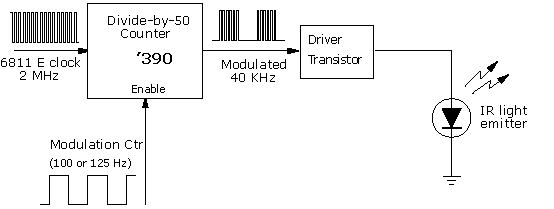 |
A special circuit is used to generate infrared emissions modulated at the 40 KHz frequency. A block diagram of this circuit is shown in Figure 5.23. The diagram shows that the '390 chip, wired in a divide-by-fifty configuration, is used to generate a 40 KHz signal from the 68HC11 E clock, a 2 MHz signal. In actuality, the '390 chip contains two decade counters. Each these consists of a separate divide-by-five counter and a flip-flop (a divide-by-two device). The '390 is wired in the divide-by-fifty function by ganging two of the divide-by-five counters and one of the flip-flops. The IR control signal is wired to the clear input of the '390 chip; when this signal is true, the counters will reset and will be prevented from counting. By modulating this signal, the 68HC11 can generate the low-frequency square wave that ends up being transmitted to the Sharp sensor. Figure 5.24 shows the full circuit schematic for the IR subsystem. The 2N4401 transistor is used to drive the infrared LEDs.
Figure 5.24: Infrared Transmission Circuit
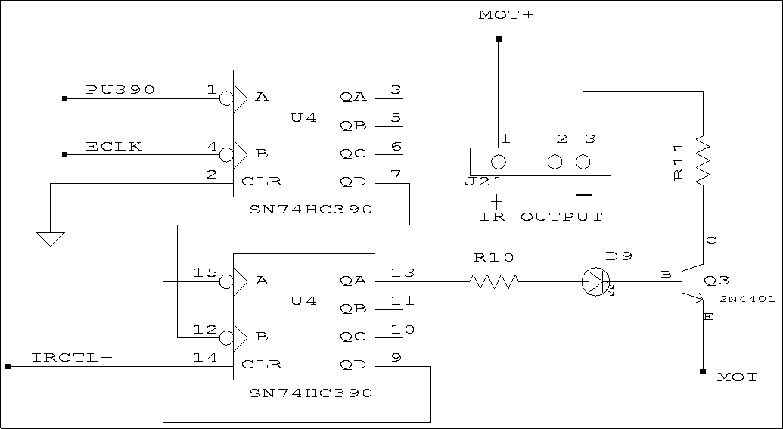 |
The IR Beacon
Figure 5.25: Infrared Beacon Circuit
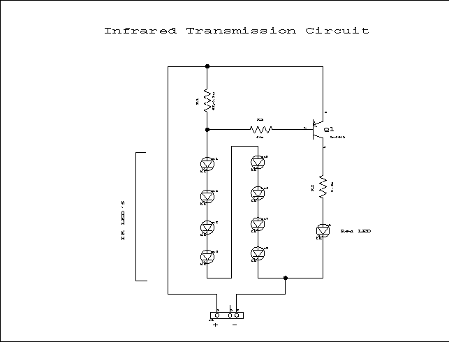 |
The IR beacon is like the remote control for your TV. The IR beacon emits a modulated signal containing information which is received and interpreted by the IR sensor and the RoboBoard. This process is much like the transmission that occurs when you press a button on the remote control. The IR beacon for ELEC 201, however, has two design challenges to tackle. Figure 5.25 shows the schematic for the IR beacon. The IR beacon must produce a signal with the maximum possible strength so that it can be easily detected, and detected at reasonable distances. Optical power output and current have a linear relationship, so in order to increase the signal strength, current must be increased. Unfortunately, increasing the current supplied to the IR board shortens the battery's life. In order to minimize the current, the IR LEDs are all wired in series. To change channels one would point the remote at the TV and press a button. The robots, though, must broadcast their signal in every direction. Again, there is a tradeoff that must be optimized. Infrared LEDs have the property that as the viewing angle increases, the radiant intensity decreases. The Sharp GL537 LEDs used on the 1999 IR board provide the best compromise between power and viewing angle and are used in commercial remote control applications. The IR board also has two indicator lights so that you can make sure everything is working. The red LED labeled IR XMIT on the RoboBoard lights up when the RoboBoard is attempting to transmit a signal. The red LED on the IR board lights up when all the IR LEDs are transmitting. The LCD Display J19 (in Figure 5.26) is a fourteen pin header designed to be compatible with a 14-pin standard LCD bus. A variety of character-based LCD devices with different screen sizes use this standard bus. The LCD bus standard is fairly simple, consisting of the following signals:
 | an 8-bit data bidirectional bus |
 | two mode select input signals |
 | a clock line |
 | a voltage reference for contrast adjustment |
 | 5 volt logic power |
 | signal ground |
In fact, reading and writing data to an LCD is much like reading and writing data to latches or to memory. There is one problem, however: LCDs only work at data transfer rates up to 1 MHz. The 68HC11 on the ELEC 201 RoboBoard operates at 2 MHz -- too fast for most LCDs. One straight-forward solution to the speed problem would be to use a '574-type latch between the 68HC11 and the LCD. The '574 could be written to at the full bus rate of the 68HC11; its outputs would drive the data bus of the LCD. A separate signal could be used to toggle the LCD's clock line, causing it to latch the data that had been written to the '574. This solution assumes that one does not need to read status data back from the LCD. An unconventional, zero-additional-hardware solution has been implemented in the ELEC 201 system, which takes advantage of an obscure feature of the 68HC11 microprocessor. The 68HC11 has two main operating modes, known as single chip mode and expanded multiplexed mode. The discussion of memory read and write cycles that has been presented in this chapter has been based on the expanded multiplexed mode, which is the 68HC11 mode that is used when external memory is part of the 68HC11 circuit. When the 68HC11 is operated in single-chip mode, the upper-eight-bit address bus and multiplexed address/data bus become general purpose inputs and outputs of the 68HC11, controllable by system software. Thus, in single-chip mode, the 68HC11 could communicate with the LCD with a software driver, rather than the too-fast hardware communication. There is a problem with this, however: when the 68HC11 is placed into single-chip mode, it can no longer execute a program from its external RAM. In fact, as far as the 68HC11 is concerned, there is no external memory. Fortunately, the 68HC11 has 256 bytes of internal RAM, from which it can execute a program when in single-chip mode. Thus, a software driver could execute out of internal RAM, perform a transaction with the LCD, and then switch back to expanded-multiplexed mode and return control to the main program in external memory. The obscure feature mentioned is not the fact that the 68HC11 has both of these modes, but the idea of dynamically switching between them. Here is the solution that has been implemented:
- 1.
- Start by copying a software driver from external system memory into the 256 bytes of internal 68HC11 memory.
- 2.
- Begin execution of the driver program located in internal memory:
 | Place the 68HC11 into single-chip mode; external memory disappears. |
 | Execute a low-speed transaction with the LCD by directly controlling the data bus via software. |
 | Place the 68HC11 into expanded-multiplexed mode. |
 | Return to the main program in external memory. |
- 3.
- Continue normal program execution.
The actual LCD driver routine buffers characters to be printed to the LCD; one thousand times per second, an interrupt routine calls the internal memory driver as described, writing a single character to the LCD. The whole process operates transparently to the ELEC 201 system user.
Figure 5.26: LCD and Piezo Circuit
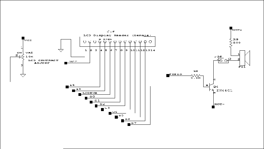 |
|
|

